This project uses the RAK3172 module as main controller (no need for AT commands from a host controller). It has inputs, hall switches, motion sensor, external memory and LoRa communication. Targeting small size and low power consumption, it can be powered by a single or double AA cell, solar panel or connected to the mains.
For the SW development I am planning to use the RUI3 APIs from RAKwirelles. Internal connectors are available to connect the ST-Link in-circuit debugger / programmer interface and serial monitors.
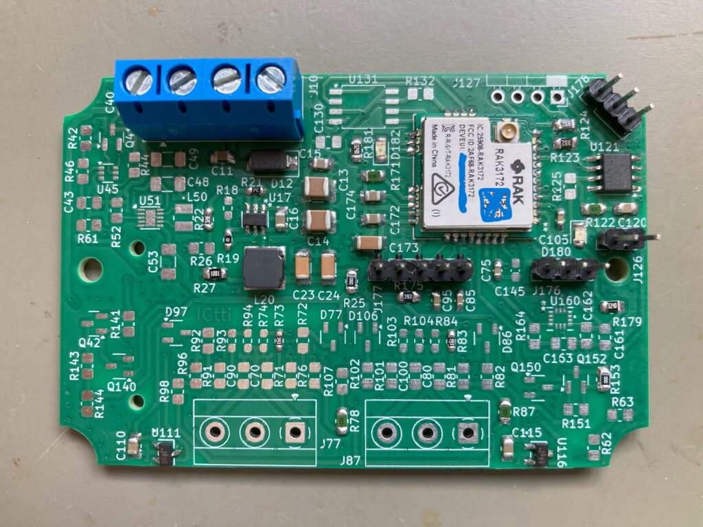
The hardware design was done with the KiCad software. It is an open source, easy to use and very good CAD tool. Really liked the results.
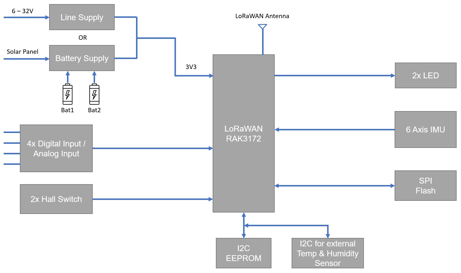
Block Diagram
Main Functions
Alternative power supply options (assembly option), reverse polarity protected: Line Supply: input voltage range from 6V to 32V, with a Buck converter to 3.3V; Battery Supply: input voltage range from 1.8V to 5.5V, with a Buck-Boost converter to 3.3V; Holder for 2 x 1.5V (series) AA batteries, 1 or 2 x 3.6V (semi-parallel) AA batteries for longer autonomy; One battery cell (Bat2) can be used as a backup for the Line Supply input.
RAK3172 module with an internal uController for the LoRaWAN stack and the application software: Arm Cortex M4 32bits MCU, with 256kB Flash and 64kB SRAM;
LoRaWAN communication, Class A, B or C according to LoRaWAN specification 1.0.4, performed by the RAK3172 module. Supported bands: EU433, CN470, RU864, IN865, EU868, AU915, US915, KR920, RU864, LA915 and AS923. Ipex 1 connector for external antenna;
Four Digital / Analog Inputs, configurable for High or Low active or 4-20mA sensor signal measurement (assembly option);
Possibility to connect the external temperature sensor ds18b20;
Two Hall effect switches, omnipolar, push-pull output;
6-Axis motion sensor, IMU (3-Axis Accelerometer and 3-Axis Gyroscope);
I2C port for external Temperature and Humidity sensor;
8kbit serial EEPROM for system configuration;
8Mbit or 16Mbit serial flash memory for data logging;